| Prev | Next |
Modeling with the UAF
With the UAF perspective selected, as shown in the "Getting Started" topic, all language features, including concepts, diagrams, and views and viewpoints, will be available to the modeler. Enterprise Architect also provides a way to create a repository structure using Packages that act as containers for the elements and diagrams you create to describe your enterprise. There is also a wide range of tools helpful in working with the UAF models, including diagram filters, legends, notes, and tools for navigating and searching, which will be particularly useful as your models become larger.
Enterprises and systems have become increasingly complex, and to achieve desired outcomes, architects, engineers, managers, and a wide range of other stakeholders must collaborate, often in distributed settings. Teamwork and collaboration are essential, as Enterprise Architecture models usually grow organically with multiple architects contributing to a central model. Enterprise Architect is fundamentally a collaboration platform that enables architects, engineers, and other stakeholders and contributors to work together, sharing ideas and utilizing discussion, review, and other collaboration features to ensure the creation of robust and relevant architectures.
Adding Diagrams
Diagrams are one of the most useful ways of communicating with other team members and with stakeholders who have an interest in the enterprise architecture. Diagrams can be created in different ways:
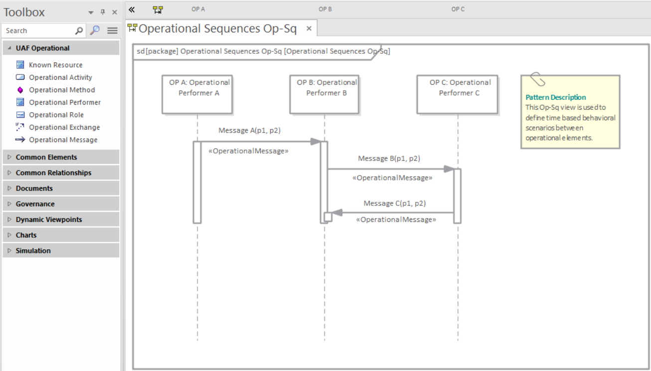
- An empty diagram can be created and existing elements can be added from the Browser window, or new elements and connectors can be added from the Diagram Toolbox
- A diagram can be created from a user-defined pattern that also contains elements and connectors
In the next section we will also explore another method by which a diagram can be created using the Model Builder tool. As a modeler you are likely to use all of these methods at different times, depending on the circumstances and the modeling context. To create a new UAF diagram you can use one of these methods, ensuring that you have first chosen the UAF perspective.
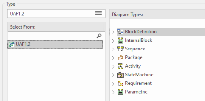
Figure: New Diagram dialog showing the UAF diagram types
Creating a Package Structure
There are two approaches to creating a suitable Package structure for your UAF models within Enterprise Architect, both of which mimic the enterprise architecture methods.
- An initial well developed Package structure that is changed very little through the course of model development for an initiative
- A skeleton model that contains the main Packages and is augmented as new needs are understood, and changed significantly during an initiative
Either of these methods can be used, or a team could consider a hybrid approach; either way new Packages need to be created in Enterprise Architect that will act as the containers for new elements and diagrams.
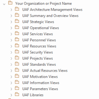
Figure: Showing the Package structure in the 'Project' panel of the Browser window.
Adding Views and Viewpoints
The Unified Architecture Framework and language defines a series of example viewpoints designed to provide representations that are meaningful and relevant to a variety of stakeholders. These viewpoints are made available in Enterprise Architect through the Diagram Builder dialog or the Model Builder patterns, which provide a way of creating both repository content and diagrams that show how the elements are connected by relationships. Thus new diagrams can be created.
- A new view can be created using the Diagram Builder dialog with restriction to the selected Viewpoint.
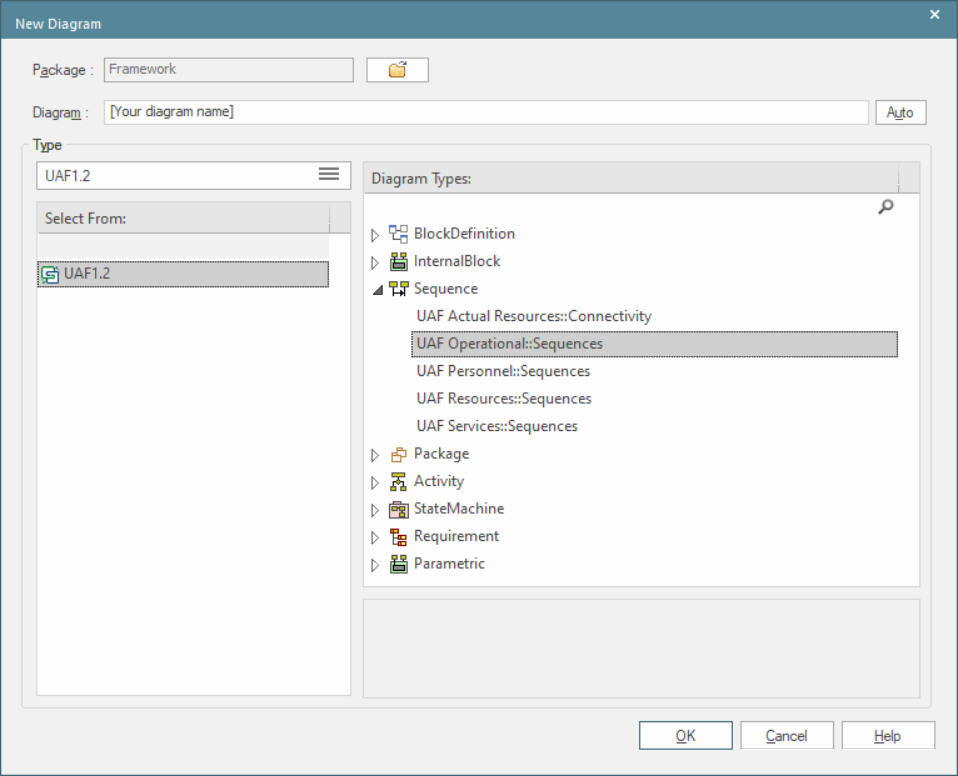
Figure: Showing the Diagram Builder dialog for the Stakeholder Viewpoint in the Motivation Viewpoints group.
- A diagram, its elements and connectors can be added using the Model Builder.
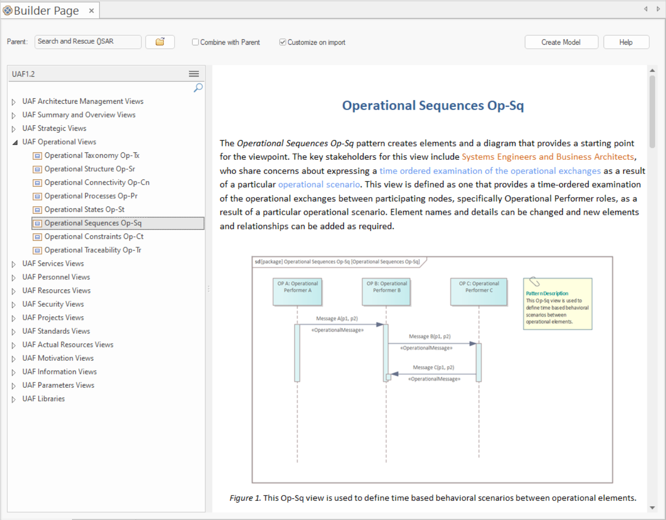
Figure: Showing the Model Builder and the Stakeholder Viewpoint in the Motivation Viewpoints group.
When the view has been created the diagram toolbox will restrict the elements and connectors to only those that are part of the viewpoint.
Adding Elements and Relationships
Elements can be added to the model directly without the need for a diagram to be created, but it is far more common for a diagram to be the device that is used to add both elements and connectors to the model. Diagrams can be built up with a combination of:
- Existing elements dragged from the Browser
- New elements (or Relationships) dragged from the Diagram Toolbox pages
Adding Elements from the Browser
This diagram shows how elements can be added from the Browser window by dragging and dropping them onto the current open diagram canvas.
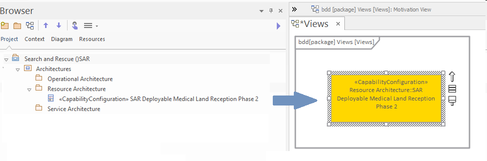
Figure: Showing an existing element being dragged from the Browser window
Adding Elements from the Toolbox
This diagram shows how elements can be added from the Toolbox pages by dragging and dropping elements (or relationships) onto the current open diagram canvas.
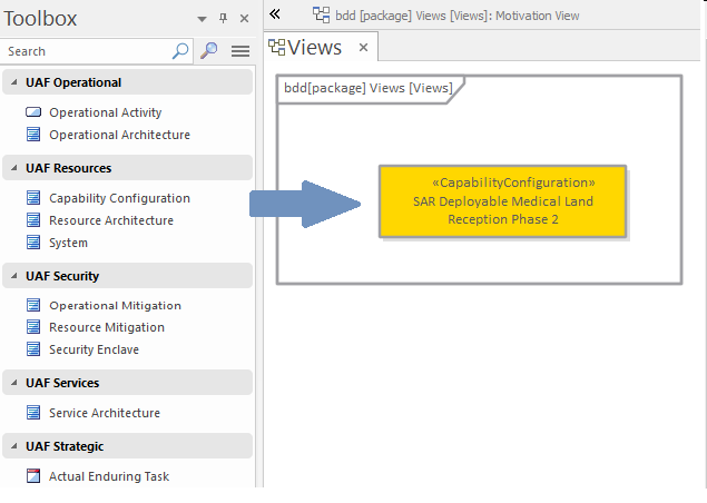
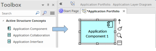
Figure: Showing an existing element being dragged from a Toolbox page
Changing Elements and Relationships
Any element or relationship can be changed including its name and properties. When a change is made to an element in any location, for example in a diagram this change will be reflected in any other diagrams (view) that contains the element or relationship.