| Prev | Next |
Interaction Overview Diagram
Interaction Overview diagrams visualize the cooperation between other Interaction diagrams to illustrate a control flow serving an encompassing purpose. As Interaction Overview diagrams are a variant of Activity diagrams, most of the diagram notation is the same, as is the process of constructing the diagram.
Decision points, Forks, Joins, Start points and End points are the same. Instead of Activity elements, however, rectangular elements of two types are used:
- Interaction elements display an inline Interaction diagram, which can be any one of the four types (Sequence, Timing, Communication or Interaction Overview)
- Interaction Occurrence elements are references to an existing Interaction diagram: they are visually represented by a frame, with ref in the frame's title space; the diagram name is indicated in the frame contents
To create an Interaction Occurrence, simply drag an Interaction diagram from the Browser window onto your Interaction Overview diagram. The ref frame displays, encapsulating an instance of the Interaction diagram.
You generate Interaction Overview diagram elements and connectors from the 'Interaction Overview' pages of the Diagram Toolbox.
Example Diagram
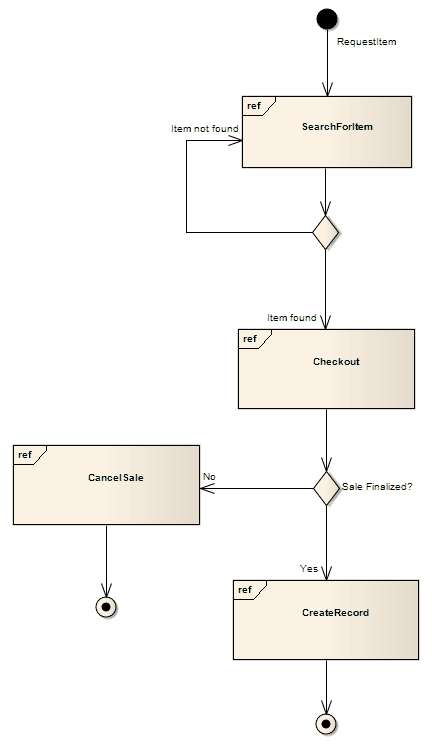
This diagram depicts a sample sale process, shown in an Interaction Overview diagram, with sub-processes abstracted within Interaction Occurrences.
The diagram appears very similar to an Activity diagram, and is conceptualized the same way; as the flow moves into an interaction, the respective interaction's process must be followed before the Interaction Overview's flow can advance.

Interaction Overview Diagram Toolbox Icons
Icon |
Description |
See also |
|---|---|---|

|
The Diagram Frame is a reference to an Interaction diagram. |
Diagram Frame |

|
The Interaction Occurrence is a reference to an existing Interaction diagram. It is displayed as a frame, with 'ref' in the frame's title space and the diagram name in the frame contents. It is used inline as an AcitivityInvocation. |
Interaction Occurrence |

|
The Control Flow is a connector connecting two nodes, modeling an active transition. |
Control Flow |
Interaction Overview Diagram Control Nodes Toolbox Icons
Icon |
Description |
See also |
|---|---|---|

|
The Initial element defines the start of a flow when an Activity is invoked. |
Initial |

|
A Decision is an element that indicates a point of conditional progression: if a condition is true, then processing continues one way; if not, then another. |
Decision |

|
A Merge Node brings together a number of alternative flow paths in Activity, Analysis and Interaction Overview diagrams. |
Merge |

|
A Synch state is useful for indicating that concurrent paths are synchronized. They are used to split and rejoin periods of parallel processing. |
Synch |

|
A Fork/Join element can be used to: 1) split a single flow into a number of concurrent flows, 2) join a number of concurrent flows or 3) both join and fork a number of incoming flows to a number of outgoing flows. |
Fork/Join Fork Join |

|
A Fork/Join element can be used to: 1) split a single flow into a number of concurrent flows, 2) join a number of concurrent flows or 3) both join and fork a number of incoming flows to a number of outgoing flows. |
|

|
The Flow Final element depicts an exit from the system, as opposed to the Activity Final, which represents the completion of the Activity. |
Flow Final |

|
The Final element, indicates the completion of an Activity; upon reaching the Final, all execution is aborted. |
Final |