| Prev | Next |
Relationships Overview
Enterprise Architect is a powerful language-compliant platform that makes it easy to create industry standard Enterprise Architecture diagrams using ArchiMate. The tool allows the modeler to work with relationships flexibly, including being able to change the styles of the connectors while at the same time maintaining the rules and constraints of the ArchiMate language, including restricting what elements can be connected together.
Allowable Element Relationships
The compliance has been achieved by building the ArchiMate facility on top of a flexible and compliant meta-model that implements the relationship table specified in Appendix B of the ArchiMate Specification. This ensures that if the specification changes it is simply a matter of updating the metamodel and all aspects of the tool will reflect the change. This makes it easy for the user to create first-class and compliant models as the interface restricts the available relationships when attempting to draw a connection between two elements in a diagram canvas.
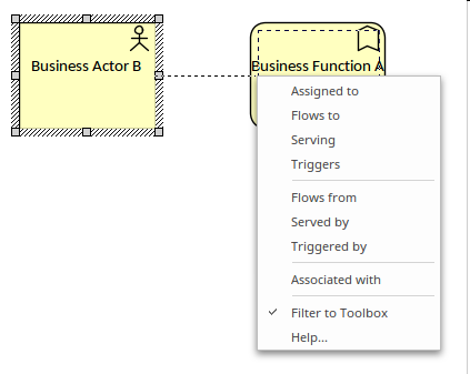
In this example we see a modeler using the Quick Linker (a fast way of connecting elements) to create a relationship from a Business Actor to a Business Function. Once the relationship is dropped onto the target a menu is opened that displays the allowed relationships between the two element types based on the direction of the connection.
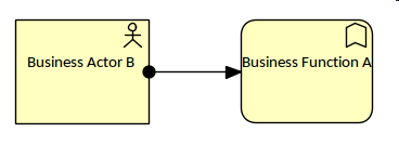
In this diagram we see that the user has selected the assignment connector, as this is an allowed relationship from a Business Actor to a Business Function.
Changing Size Colour and Style
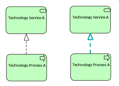
Any of the standard ArchiMate relationships can be changed to different sizes and colors without affecting the meaning or syntax of the diagrams. Enterprise Architect provides great flexibility for changing the relationships and elements, and the diagram styles and themes. This illustration shows two different diagrams where the same relationship has been rendered in a different line width and color.
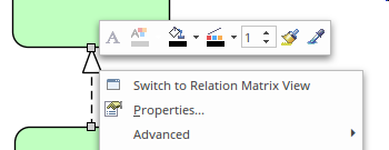
The options to change the style of a relationship are available from a number of locations, including the ribbons and the element Quick Style icon that is displayed when the relationship's context menu is selected in the diagram. This illustration shows the options available from the diagram.
Nesting
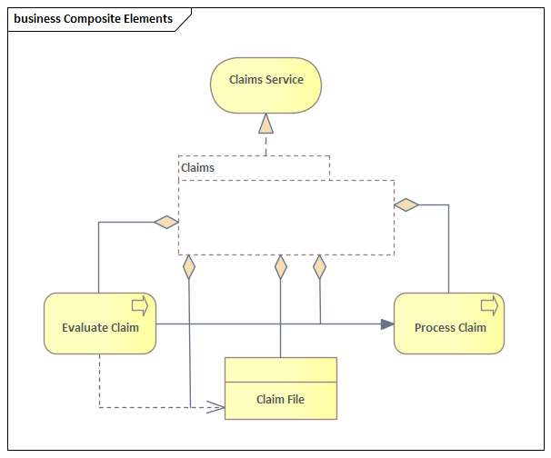
Enterprise Architect allows elements to be nested as an alternative way of representing relationships. This is a powerful and compact notation for some diagrams, alleviating the issue of some stakeholders finding the ArchiMate visual syntax difficult to interpret. It does, however, introduce ambiguities when the diagrams are viewed outside the tool. This is an issue with the ArchiMate language itself rather than being any limitation of the tool, and while the diagrams are being viewed inside Enterprise Architect the ambiguities can always be resolved. Enterprise Architect allows nested views to be created and visualized, providing a number of ways to remove the ambiguities by use of other windows that can be opened in the workspace; these clearly indicate the type of relationship implied by the element nesting.
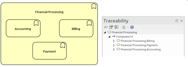
To create nested elements, the relationships between elements must already exist or first be created. A modeler can then use drag-and-drop to nest one or more elements inside another element. Enterprise Architect hides the relationships in the diagram but they are visible through a number of other workspace windows, including the Traceability window, the Relationships window and the 'Details' tab of the Inspector window. This illustration shows the Traceability window when the containing element is selected, clearly showing the Composition relationships that exist in the model; these are not displayed as direct relationships in the diagram but are indicated by the nesting.
Connecting to Other Relationships
Enterprise Architect, in compliance with the ArchiMate specification, allows you to connect one end of certain relationships to other relationships. This is powerful device to express particular modeling concepts; for example, the data that is transmitted between two elements such as two Application Components or Business Functions. This diagram shows two examples where this feature has been used.